Not Quite Nixie
This is a post I’ve dug up from the depths of the old website. It was so well hidden that hardly anybody ever found it – at least that’s what the logs say.
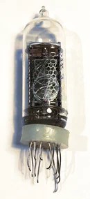
For a couple of years, I’ve had six Nixie tubes in my workshop. I originally bought them off a Soviet surplus electronics dealer, as they’re not made anymore, so they can be considered antiques. I’ve always wanted to build a clock or some other number-displaying-device-thing out of them, but they have one problem: In order to make them glow, they require a voltage far higher than I’m equipped for and comfortable tinkering with – around 200 V.
Right after I first engraved something into acrylic for edge-lighting, I thought about layering several of those engraves. My first idea was to create a full colour image by lighting three component channel images in red, green and blue. I haven’t tried that yet. My next thought was “Hey, if I stack ten numbers with individual LEDs…”, and the idea was born.
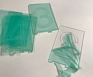
The thinnest acrylic I found was 2 mm extruded, so I started my experiments with this. First attempts were put together with individual LEDs per slice, which meant controlling the display used an uncomfortably large number of data lines on the microcontroller – ten per digit and that’s just for one colour. I started to work around this by using one or more 74HCT595 shift registers. This reduced the interface to three data lines – latch, data and clock – regardless of the number of digits, since the registers could be daisy-chained. It still meant a lot of soldering though…
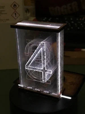
…then I discovered WS2812B LEDS. These come as single units or – as I used them – on strips. The LEDs each have their own IC on board that not only lets you turn them on or off individually, but also lets you set an separate colour per serially connected LED, all over just one data wire. I ordered a couple of metres from the Chinese electronics supplier of choice and ran into the next problem: The LEDs are spaced at about 4.5 mm. I first experimented by laying the strip diagonally to reduce the effective spacing along the edge of the acrylic stack to roughly 2 mm, but that meant that the individual numbers would be too large to fit ten on a sheet of acrylic. I eventually put an air gap between the acrylic layers, allowing each layer to line up with one LED. This way, I could fit ten LEDs on the limited horizontal space I had. This meant more soldering again.
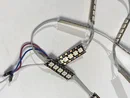
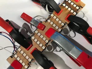
These are eight strips of five LEDs each soldered together to form a 40-LED unit, which I then glued into a laser-cut MDF frame which goes underneath the acrylic numbers. The display I’m building therefore has four numbers, which will work splendidly to display the time. It is intended as a proof of concept, but it might just as well serve a purpose as a desk clock. If I had started the project from scratch today, I would have added a fifth stack with weather symbols (clouds, sun etc.) for additional display possibilities.
The next question was which microcontroller I would use for the display. As I’m using it as a clock, I first thought of an Arduino with an added RTC module to survive reboots. This would have made it necessary to add buttons to set the time, and I wanted to keep the project as clean as possible on the outside – ideally, just a cable for power.
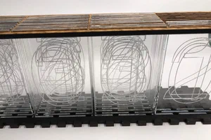
After some consideration, I settled on an ESP8266. This has built-in Wi-Fi, so I don’t need an accurate real-time clock; I can just synchronise the clock with the network. As I’m now using only one data line for all four number units, an ESP-01 would have been enough.
In the end, I decided on a NodeMCU-v3, as this has a built-in USB connector and supplies 5 V DC directly. The 3.3 V of the ESP-01 is not reliably within specification for the LEDs, and having 5 V on tap beats mucking about with op-amps, level shifters or the like. To top it off, I could program it in MicroPython, which I’m more comfortable with than the C dialect used by Arduino boards.
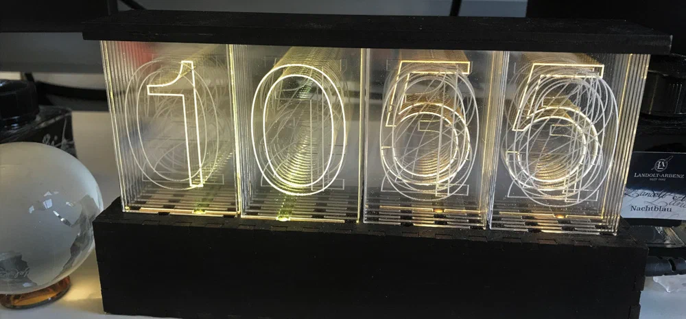
This is the final prototype – boxed into MDF, painted with black acrylic paint, and standing on my desk at work. Looking at it every day, I’m very much reminded that it is, after all, still a prototype. Here are the things I want to change for the next model:
- Timekeeping: The current model synchronises the time from my phone on startup – that’s it. As the real-time clock of the ESP8266 isn’t the most accurate (to put it mildly), I have to reboot the clock often to keep accurate time. I’ll have to introduce either a separate RTC, a regular synchronisation process or a way to trigger it manually.
- Colour keyframes: Currently, the colours of the numbers are fixed, with the minutes blinking between a slightly brighter and darker shade of orange to mimic real Nixie tubes. I’d like to introduce a way to have the colours definable by time – for example, white at 12:00 and blue at 13:00 – with the display smoothly interpolating between them.
- While we’re on buttons: Four digits could also display a date, so a button to switch between time and date could also be implemented. To keep the design clean, a capacitive touch panel inside the case would be nicer than a clunky piece of electromechanical heritage.
- Mechanical redesign: The panels have an air gap between them. At the moment, this isn’t too much of a problem, but once dust starts to gather between them it could be. The next iteration will probably be bigger and made out of 3mm acrylic; that should allow me to sandwich the panels without any gaps.
So, while I like the first prototype, I’m not in danger of running out of potential improvements quite yet. I’ve already had first requests to buy the clock, but before I get to that stage I’ll want a better model. Watch this space…